| Electrical Diagnosis Tips | Baked
Engine Wiring
Dielectric vs. Conductive Grease to Protect Connectors and Grounds Circuit Board and Contact Repair |
Wiring Fault Diagnostic Tips.
[Tips from Import Car Magazine]
DIAGNOSTIC THOUGHTS
Wiring failures occur as open, shorted
or short-to-ground (grounded) circuits. An open circuit, obviously, is
a broken or disconnected wire. Shorted circuits occur when the insulation
between two wires fails. Grounded circuits occur when a bare wire is allowed
to touch the vehicles powertrain, sheet metal or frame. As for narrowing
diagnostic probabilities, lets remember that:
1. Before wasting hours of expensive diagnostic time, test all fuse circuits with a DVOM or approved test light. Remember that fuses can fail without showing signs of an obvious burn-through. Since a loose or corroded fuse connector may also cause many intermittent circuit failures, thoroughly inspect and clean the fuse circuits before proceeding with your diagnosis.
2. Most wiring failures occur at either end of the wire as a bad connection. Although splice failures inside the wiring harness are rare, some nameplates are notorious for splice failures. Technical service bulletins (TSBs) and Internet sources offer valuable insight to typical nameplate problems.
3. Corroded harness connections cause most intermittent circuit failures. Simply unplugging the connector and applying an electrically compatible corrosion inhibitor will repair most connector failures.
4. When diagnosing intermittent failures, remember that suspect turn signal flashers, fuses, bulbs and relays can be replaced more cheaply than they can be diagnosed. When diagnosing an intermittent lighting failure, for example, I always begin by cleaning the bulb sockets and installing new bulbs. How much diagnostic time are you willing to spend testing a $0.98 light bulb thats nearing the end of its practical service life?
5. Engine, computer and body ground connections should be checked first, especially if the vehicle has recently visited the collision repair shop.
6. Keep in mind that most electrical systems, when left untouched, perform very reliably. When they do fail, the failure will be predictable, such as a bad current or ground connection, blown fuse and the like. Most predictable failures can be solved within a two-hour time block.
7. On the other hand, the DIY mechanic "short-testing" a cooling fan switch or fuel pump relay can create a multiple failure with unpredictable consequences like burning a wire within a wiring harness. Obvious tampering should always create a red flag... Electrical "red flags" may include newly installed sound systems, electrical accessories, trailer brakes, auxiliary lighting and the like...
8. Many circuits serve more than one accessory or function. Years ago, for example, I found that a burned brake light fuse was caused by a loose courtesy light in the ashtray. Without a good magnetic short detector, the problem would have been difficult to solve since a relationship between a brake light and ashtray light isnt immediately logical or clear, to say the least. In other unlikely cases, Ive found an instrument cluster fuse that also supplies field current to the alternator. The moral is, never rule out the effect of one circuit upon another...
10. In fact, avoid using test lights altogether. When testing fuses, for example, I use an LED-type test light (available from a major tool manufacturer) that indicates open or grounded fuse circuits and voltage availability. This eliminates guesswork and protects ground-sensitive electronic circuits like air bag sensors.
11. Use a professional DVOM with a min/max voltage feature and alarm to test intermittent failures. The min/max feature will record the highest voltage reached in the circuit and sound an alarm each time a higher voltage is reached. For the technician working alone, this feature is a real time saver, especially when performing a "wiggle" test on an intermittent wiring problem. In the same sense, lab scopes are particularly useful to find loose ground connections. During a wiggle or vibration test, loose ground connections will show up as a voltage spike in an otherwise zero-volt lab scope waveform.
12. Remember how hard it is to find the trim screw driven through a wiring harness hidden underneath a headliner? A good short detector will help you quickly locate concealed short-to-ground circuits. For about 30 bucks, its a great time saver for you and your customer alike.


In 960 cars, the relays are in the same location but mounted on a vertical relay board.
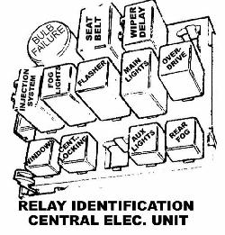
Relay Identification in UK 760 Model.
[Query] I need the relay identification on the relays which are located
on the side of the transmission tunnel under the plastic panel in the passenger
footwell compartment. These relays are labeled A,B,C,D,E,etc. No
disrespect ,but please do not refer to the ones in the compartment behind
the ashtray because I do not have that model. [Response: Steve]
In my 1990 760gle United Kingdom model the relays are A: main lighting(part);
B: motronic/jetronic relay; C: central locking relay; D: foglamp
relay; E: main lighting relay(part); F: bulb failure warning
relay (front); G: overdrive relay; J: power boost relay;
K: rear wiper delay relay; L:windscreenwiper delay relay; M: seat
belt warning relay. A, B, F, J, L, and M are permanently attached
to the board.
[Don Foster:] Over time (like 10
years), the solder used in production manufacturing tends to become crystallized
and cracks. The type of solder used in high-volume production is different
than that used in an electronics repair shop. The problem with the relays
is tiny, almost invisible microscopic cracks in the solder. These cracks
usually encircle one (or several) heavy connections, such as from the relay
or a main lug connector. Under a bright light, and using a magnifying
glass, inspect the soldered connections. Simply resoldering these circuit
board very often restores them to perfect performance, and it's a whole
lot better (and cheaper) than a $50-$100 replacement part. I have recovered
literally dozens of Bosch relays (OD, fuel pump, wipers) to perfect performance
this way at $0. In fact, I resoldered ALL the relays in my family's 6 Volvos
before a failure stranded us.
[Symptom: Window does not raise or lower.] [Diagnosis:] Switch. These are fun to fix. Pull the switch assemblies out of the door handle (two metal springs at front and back hold them in: use a screwdriver to lever them out. Then pop the switch out (I usually wind up doing them all as long as I'm there) and pry the side off the little nipples so the cover comes off each switch. Be careful since there is a spring in the rocker, you don't want to lose it. Take out the little metal "lever" and use some very fine sandpaper to neaten up the contacts on the lever and the contact points inside the switch. [Tip from John Yuristy] . I wouldn`t use sandpaper or steel wool on contacts, some are just plated and you will remove the good stuff.
[Response:Steve Ringlee] For a detailed
analysis of the window switches, take a look at Michael Ponte's analysis
at http://www.mikeponte.com/volvo/pwin.htm.
Another solution is disassembling the switches (be careful in removing
them from the black plastic holders), de-oxidizing and cleaning them using
an electronic de-oxidizer such as DeOxIt from Caig Labs, then using a fine
Scotchguard nylon scrubber to burnish the contacts, and finally reassembling
them using Caig ProGold protective coating (very small quantities precisely
applied) on the contacts to prevent further dirt and oxidization from ruining
the contacts. Caveat: I have tried the "rebuild" approach on these
switches and found that it did not last that long; I ended up buying a
new driver's door switch from RPR for around $30 just to save more work.
[Quick preventative:] Watch the wires coming from the connector directly under the windshield below the driver and the oil pressure and alternator wires on the right front of the motor. These are the first ones to go. If it starts reroute the alternator wire first as this can cause the most damage if left in the harness. Then replace the starter, then the coil wire as these have the next greatest potential for damage. If you can, get the wires replaced before they cause other damage, do so as the cost will come out of your pocket.
[1983-1987 7xx cars:] If you are referring to the problem of wiring harness rot that affects the 83-87 models, it usually affects the harness on the engine. On the LH cars, this usually includes a fuel injection harness and a separate ignition system harness. However, I have seen some deterioration of other underhood harnesses including the wiring that goes to various lights (turn signals, corner markers, headlights, etc.
[Advice on replacement:] The engine wiring
harness went bad on my 1983 240 Turbo (170,000). I noticed it first when
my starter would try to engage occasionally when I hit a bump or turned
a hard right. The wires up by the firewall on the left side of the car
were bare at the connector. I tried to separate and tape them, but that
did not work. I found out why when I replaced the harness. The harness
runs along the left side of the block, and EACH of the wires was completely
bare the majority of the length of the block!! As you know, depending on
which ones touched which, anything could happen. REPLACE the whole harness!!!!!!
Trying to patch it will only lead you into hours and hours of nightmares
both as you attempt to cob it together, and as soon as moisture gets in
your cheesy butt connectors and your gauges, idle, starter, etc go wacky!!!
Remember: My Volvo is Turbo. Although
a similar process, I can not speak directly on the naturally aspirated
version. The job took me (a former diesel mechanic but working with limited
tools on this job) 5 hours. I unbolted the intake and pulled it away from
the head. Of course to do this you will need an intake gasket. I recommend
you do this also, as to work around and under the intake would be treacherous.
With the intake pulled away, you can see straight down in there. You may
want to replace your flame trap when you are in there as you have a straight
shot at it. Any troublesome vacuum lines could easily be swapped out also.
The new Volvo harness is color coded exactly
as the original. (big advantage). It is also exactly correct in length.
(huge advantage). Just remove the old one, being careful at each connection
- temp sensors, alt, oil press, etc. are all very dry. You may have to
cut the old harness out in pieces as it is not pliable at all. Install
the new one by starting at firewall and working your way along the block
and around to the oil press and alternator. It is pretty self explanatory
really. Leave about 5 hours to do it. This sounds like a lot, but multiply
it times the hourly rate of your local shop, or the cost of burning up
a starter (and a tow) like I did, and you will have a little more incentive
to clear up some time on Saturday morning. No special tools. (May want
torque wrench for intake if you are REALLY particular). I shopped all over
and I purchased it from NILS SEFELDT Volvo in Houston Texas (281) 721-1600
(800) 468-0041 fro $230.22 and the gasket for $11.70. [Additional tips
from Dick:] My suggestion: do not remove the intake manifold on the
700 series. Remove AMM and hose to intake, idle speed motor and hoses,
also flame trap and oil trap. Label stuff carefully. Begin your rewire
from under the car, ie the oil pressure sender light, removing the old
stuff as you go. Your new harness has yellow bands indicating where the
clamps should be. Remove the harness from the AMM and replace with
new. You will have to remove the knock sensor wiring and mark it .
I think you get the picture. With the oil trap removed, you can clean it
and put a new O ring on it (leak source) and new flame trap. Other suggestion
is to remove the 3 plug ins on the passenger side and pull then through
and under the manifold along with the injector harness stuff.
Believe marking and labeling is extremely
important. I blew the brains out of a 240 by mixing up two similar 3-prong
connectors. Label the old harness too because you can always compare wire
colors in the connectors that are alike.
[More from a VCOA Wiring Clinic, courtesy of the BrickBoard:]
Scope: The problem afflicts 200 and 700 series Volvos manufactured during the period 1983-1987 [Note: several commentators would also include the 1981 & '82 models of 240 series.]. The problem has also appeared in other vehicles manufactured during the same period with Bosch electrical systems. Owners of all vehicles manufactured with Bosch electrical systems during the period should inspect the engine wiring harness. Anyone considering purchase of such a vehicle should inspect the engine wiring harness if the harness is the original.
Presentation of problem: Disintegrating insulation on wires exposed to high temperatures for long periods (10 years or more).
Symptoms: All vehicles within scope are vulnerable to the problem. Close inspection of the engine wiring harness will reveal the problem before it causes short circuits. If a vehicle within scope exhibits drivability problems that are intermittent and cannot be otherwise diagnosed, short circuits in wiring harness caused by deteriorating insulation may be the cause.
Inspection: Use a strong light source and check wiring, paying particular attention to wiring passing close to high heat sources. High heat sources include intake manifold, exhaust manifold, turbocharger, block, firewall.
Common locations presenting problem: B23: firewall near main connector, alternator, intake manifold. B230: ground wires on intake manifold, oil pressure sender, water temperature sensor on block. B28/280: no engines were available for inspection.
Solutions:
Temporary solutions: liquid electrical
tape, applied in several coats over several hours, good between -20 and
255 degrees F; shrink-fit insulation, applied with heat gun or torch, good
past 400 degrees F, but hard to fit correctly over end connectors; spliced
wiring, recommended by some Swedishbricks and SAAB list members as the
most nearly permanent fix that does not require a new harness. Standard
electrical tape is at best a one-month reprieve. Any solution short of
splicing
lasts no more than a few months.
Permanent solution: new wiring harness, cost ranges between $250 and $350 (US). VCOA has been successful in persuading Volvo to lower the price of its wiring harnesses for vehicles within scope, and current price range quoted above reflects those reductions. Prices have been cut from 33%-50% from previous levels (Example: old price of engine harness for B230FT engine was approximately $500, now reduced to $270). Dealers who offer club discounts will add their standard discount to the current prices. It is absolutely critical that you order the correct harness. Very difficult to do when there are 3-4 variants out there, yet little way to tell the harnesses/engine applications apart.
Workability: Owners who prefer to have a mechanic install the new wiring harness can expect to pay 4-6 hours of shop time for the job. Owners who prefer to do the job themselves should set aside one or two days. For the B230 engine, it is recommended that the owner have all vacuum hoses replaced at the same time, as well as fuel injector seals. In addition, performing the job on the B230 engine involves removal of the intake manifold and air intake valve, and so requires replacement of the intake manifold gasket and the air intake valve gasket. Owners who have replaced wiring harnesses of B23 and B280 engines may wish to offer advice on other maintenance that should be performed at the same time, as well as other parts (besides the wiring harness) that may be required. Dielectric grease for multi-pin connectors, as well as an oxidation inhibitor for single connection points to aluminum ground, are recommended. Do not interchange the two, as dielectric grease is an insulator, while oxidation inhibitor is a conductor.
Picture References. Check
out http://www.homestead.com/volvo2/harness.html
for visual images and instructions for
wiring harness replacement and other maintenance items.
For a good overall discussion of Volvo
electrical system grounds, see the article Volvo Electrical System Service:
In Search of Good Grounds, Bob Kraft, ImportCar magazine, December 1997
at
http://www.underhoodservice.com/
(see
their searchable archive for ImportCar Magazine.)
It is important to note that on all Volvos, the Oxygen sensor signal lead carries a very low voltage (0.2v - 0.8v) and the dielectric grease must NOT be used on this lead as it will interfere with the signal voltage.
For the GROUND connections - especially
those in the engine compartment where the ground leads are fastened to
aluminum surfaces like the intake manifold, I recommend using one of the
conductive greases like OxGuard. These are found at electrical supply houses
and are typically used by electricians to treat the end of aluminum electrical
cables to prevent the very high resistance aluminum oxide from forming
at connections - this was a common cause of house fires. The same high
resistance oxide plays havoc with engine management system signal voltages.
You can eliminate the problem by cleaning the aluminum surfaces and treating
with the conductive grease. Also note that many of the spade type crimp
on terminals that are available are made of aluminum. It is very difficult
to find copper ones. [Note: see also the note on greasing connectors under
Engine Tune, Performance.] DON'T use OxGuard on engine or chassis electrical
connectors or sensors.
I usually solder the heavy connections
using a soldering gun (but carefully, because these deliver a lot of heat
quickly, and can damage a PCB). The smaller solder connections are best
done with a small 25-Watt iron. Of course, you must use electronic solder,
not plumbing solder (which contains an acid-based flux).